

Zero-Order-Hold leg#
The Zero-Order-Hold (ZOH, parameterized by the cut parameter) trajectory leg is implemented in pykep as pykep.leg.zoh. The method is described in [IHA+26] as a ZOH \(_\alpha\) transcription. Conceptually, it extends the Sims-Flanagan leg by modeling thrust as a piecewise-constant continuous acceleration over each segment, while supporting generic dynamics and nonuniform segment durations.
Let the mesh contain \(n\) segments, with initial and final states \(\mathbf{x}_0\) and \(\mathbf{x}_n\) at times \(t_0\) and \(t_n\), and time grid \(\{t_k\}_{k=0}^{n}\). On each segment \(k\), the control is $\( \mathbf{u}_k = [T_k,\ i_{x,k},\ i_{y,k},\ i_{z,k}], \qquad k=0,\ldots,n-1, \)\( where \)T_k\( is the thrust magnitude and \)(i_{x,k}, i_{y,k}, i_{z,k})\( specifies the thrust direction in the selected frame. The full control vector is \)\mathbf{u}=[\mathbf{u}0,\ldots,\mathbf{u}{n-1}]$.
The cut defines \(n_{\mathrm{fwd}}=\lfloor n\,\mathrm{cut}\rfloor\) forward segments and \(n_{\mathrm{bck}}=n-n_{\mathrm{fwd}}\) backward segments. Both endpoint states are propagated to the matching time \(t_c=t_{n_{\mathrm{fwd}}}\), and the leg returns the single mismatch constraint $\( \mathbf{m}=\mathbf{x}_{\mathrm{fwd}}(t_c)-\mathbf{x}_{\mathrm{bck}}(t_c), \)\( where the two states are obtained by forward and backward propagation, respectively. Feasibility requires \)\mathbf{m}=\mathbf{0}$. The class provides the analytical Jacobians of this mismatch with respect to the endpoint states, controls, and time-grid variables, making it suitable for gradient-based trajectory optimization (including multiphase and moving-endpoint formulations).
We start with the required imports:
import pykep as pk
import heyoka as hy
import numpy as np
import pygmo as pg
from copy import deepcopy

#%matplotlib ipympl
%matplotlib inline
# Tolerances used in the numerical integration
# Lower tolerances are faster but less accurate (required tolerance depends on regime).
tol=1e-10
tol_var = 1e-6

# Instantiate ZOH Taylor integrators for Keplerian dynamics (provided by pykep).
# Contract with leg.zoh: state dimension = 7; first 4 parameters are controls;
# variational dynamics are first-order sensitivities w.r.t. state and controls.
ta_global = pk.ta.get_zoh_kep(tol)
ta_var_global = pk.ta.get_zoh_kep_var(tol_var)

# Non-dimensional units (the ZOH Taylor integrator in pykep expects MU=1).
L = pk.AU
MU = pk.MU_SUN
TIME = np.sqrt(L**3/MU)
V =  L/TIME
ACC = V/TIME
MASS = 1000
F = MASS*ACC
1 - Validate the Zero-Order-Hold leg#
We first validate the implementation by comparing analytical gradients from pykep.leg.zoh against finite-difference estimates.
This section also illustrates the standard construction workflow: define boundary states, build controls and time grid, instantiate the leg, then query constraints and Jacobians.
We start with two helper functions used for numerical differentiation:
# This assumes a copy of the leg, since it modifies one of its attributes.
def compute_mismatch_constraints_n(leg_mod, name, values):
    setattr(leg_mod, name, values)
    return leg_mod.compute_mismatch_constraints()
We now instantiate a representative leg by selecting the number of segments, the cut, the effective exhaust velocity, and the control vector.
To obtain physically meaningful endpoints, we construct them from a Lambert transfer between two Solar System planets. This choice is only for realism in the example; the method itself is general.
# Create a Lambert leg
t0 = 10000
t1 = 10400
pl0 = pk.planet(pk.udpla.jpl_lp("Earth"))
pl1 = pk.planet(pk.udpla.jpl_lp("Mars"))
r0, v0 = pl0.eph(t0)
r1, v1 = pl1.eph(t1)
# We create some starting conditions from a Lambert arc
l = pk.lambert_problem(r0=r0, r1=r1, tof = (t1-t0) * pk.DAY2SEC, mu = pk.MU_SUN)
m0 = 1000
m1 = 1000

# leg random data
nseg = int(np.random.uniform(4, 20))
nseg=10
veff = np.random.uniform(4000, 8000) * pk.G0
controls = np.random.uniform(-1,1, (4*nseg,))
controls[0::4] /= (F)  # force will be in [-1, 1] N
controls[0::4] = np.abs(controls[0::4]) # force will be in [0.s, 1] N
cut = np.random.uniform(0,1)

# putting all in nd units
state0 = [it/L for it in r0] + [it/V for it in l.v0[0]] + [m0/MASS]
state1 = [it/L for it in r1] + [it/V for it in l.v1[0]] + [m1/MASS]
veff_nd = veff / V
tgrid = np.linspace(t0*pk.DAY2SEC/TIME, t1*pk.DAY2SEC/TIME, nseg+1)

# Setting the integrator parameters
ta_global.pars[4] = 1. / veff_nd
ta_var_global.pars[4] = 1. / veff_nd

# Instantiate the leg
leg = pk.leg.zoh(state0, controls.tolist(), state1, tgrid, cut = cut, tas = [ta_global, ta_var_global])
#leg = pk.leg.zoh_py(state0, controls.tolist(), state1, tgrid, cut = cut, tas = [ta_global, ta_var_global])
We now compute and store the analytical Jacobians of the mismatch constraint.
grad_an_mc = leg.compute_mc_grad()
… and compare with numerical estimates. We use pagmo finite differences as a consistency check.
# Compare analytical mismatch Jacobians with finite-difference estimates.
for name, grad_an in zip(["state0", "state1", "controls", "tgrid"], grad_an_mc):
    leg_copy = deepcopy(leg)
    values = getattr(leg, name)
    estimate_options = {"dx": 1e-8} if name == "controls" else {}
    grad_num = pg.estimate_gradient(
        lambda x: compute_mismatch_constraints_n(leg_copy, name, x),
        values,
        **estimate_options,
    ).reshape(len(leg.state0), -1)
    print(name, np.linalg.norm(grad_num - grad_an))
state0 4.40394491084e-08
state1 2.04572042305e-06
controls 1.05657505592e-06
tgrid 1.5640934968e-07
The differences are small and consistent with finite-difference truncation/roundoff errors. In practice, analytical Jacobians are preferable for accuracy and efficiency.
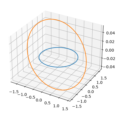
We can now visualize the stitched forward/backward trajectory segments, together with the planetary orbits.
ax = pk.plot.make_3Daxis()
pk.plot.add_planet_orbit(ax, pl0, units=pk.AU)
pk.plot.add_planet_orbit(ax, pl1, units=pk.AU)
fwd, bck = leg.get_state_info(100)
for segment in fwd:
    ax.scatter(segment[0,0], segment[0,1], segment[0,2], c = 'blue')
    ax.plot(segment[:,0], segment[:,1], segment[:,2], c= 'blue')
for segment in bck:
    ax.scatter(segment[0,0], segment[0,1], segment[0,2], c = 'darkorange')
    ax.plot(segment[:,0], segment[:,1], segment[:,2], c= 'darkorange')

ax.view_init(90,-90)
---------------------------------------------------------------------------
ValueError                                Traceback (most recent call last)
Cell In[7], line 4
      1 ax = pk.plot.make_3Daxis()
      2 pk.plot.add_planet_orbit(ax, pl0, units=pk.AU)
      3 pk.plot.add_planet_orbit(ax, pl1, units=pk.AU)
----> 4 fwd, bck = leg.get_state_info(100)
      5 for segment in fwd:
      6     ax.scatter(segment[0,0], segment[0,1], segment[0,2], c = 'blue')
      7     ax.plot(segment[:,0], segment[:,1], segment[:,2], c= 'blue')

ValueError: too many values to unpack (expected 2)
2 - Use with arbitrary dynamics#
A key feature of pykep.leg.zoh is that it is not restricted to Keplerian Cartesian dynamics. Any dynamics compatible with the interface can be used (e.g., CR3BP, equinoctial dynamics, higher-fidelity models).
The state dimension is not fixed by the leg. Set dim_dynamics and provide endpoint states and a nominal Taylor-adaptive integrator with that same state dimension. If there are \(c=\texttt{dim\_controls}\) controls, the first \(c\) nominal-integrator parameters are the segment controls; the integrator must have at least \(c\) parameters. Any remaining parameters may be used by the supplied dynamics.
If a variational integrator is provided, it must implement first-order sensitivities with respect to the \(d=\texttt{dim\_dynamics}\) state variables and the \(c\) controls. Its state dimension is therefore \(d+d^2+dc\), and it must expose the same number of parameters as the nominal integrator. The leg constructor defaults to \(d=7\) and \(c=4\), but both dimensions can be set to match other dynamics.
In the CR3BP example below, \(d=7\) and \(c=4\), so the variational integrator has \(7+7\times7+7\times4=84\) states. The first four parameters are, specifically for these example dynamics, hy.par[0]=T_norm, hy.par[1]=i_x, hy.par[2]=i_y, and hy.par[3]=i_z.
In pykep, compatible integrators are already provided (e.g., pykep.ta.zoh_kep, pykep.ta.zoh_eq, pykep.ta.zoh_cr3bp and their variational counterparts).
Below, for didactic clarity, we explicitly define a CR3BP ZOH dynamics, even though pykep.ta.zoh_cr3bp could be used directly.
# The symbolic variables.
[x, y, z, vx, vy, vz, m] = hy.make_vars("x", "y", "z", "vx", "vy", "vz", "m")

# Naming the system controls
T_norm = hy.par[0]
i_x, i_y, i_z = hy.par[1], hy.par[2], hy.par[3]
# Naming the system parameters
# Naming the system parameters
c = hy.par[4]  # 1/veff
mu = hy.par[5]

# Distances to the bodies.
r_1 = hy.sqrt(hy.sum([pow(x + mu, 2.0), pow(y, 2.0), pow(z, 2.0)]))
r_2 = hy.sqrt(hy.sum([pow(x - (1.0 - mu), 2.0), pow(y, 2.0), pow(z, 2.0)]))

# The Equations of Motion.
xdot = vx
ydot = vy
zdot = vz
vxdot = (
    2.0 * vy
    + x
    - (1.0 - mu) * (x + mu) / pow(r_1, 3.0)
    - mu * (x + mu - 1.0) / pow(r_2, 3.0)
    + T_norm * i_x / m
)
vydot = (
    -2.0 * vx
    + y
    - (1.0 - mu) * y / pow(r_1, 3.0)
    - mu * y / pow(r_2, 3.0)
    + T_norm * i_y / m
)
vzdot = -(1.0 - mu) * z / pow(r_1, 3.0) - mu * z / pow(r_2, 3.0) + T_norm * i_z / m
mdot = (
    -c * T_norm * hy.exp(-1.0 / m / 1e16)
)  # the added term regularizes the dynamics keeping it differentiable

dyn = [
    (x, xdot),
    (y, ydot),
    (z, zdot),
    (vx, vxdot),
    (vy, vydot),
    (vz, vzdot),
    (m, mdot),
]

ta_cr3bp = hy.taylor_adaptive(dyn, tol=tol, pars=[0.0, 0.0, 0.0, 0.0, 0.0, 0.01])
vsys = hy.var_ode_sys(
    dyn,
    [x, y, z, vx, vy, vz, m, hy.par[0], hy.par[1], hy.par[2], hy.par[3]],
    1,
)
ta_cr3bp_var = hy.taylor_adaptive(
    vsys,
    tol=tol,
    compact_mode=True,
)
The model is standard CR3BP augmented with thrust acceleration and a (regularized) mass-flow equation. To satisfy the ZOH parameter contract, we reserve par[0:4] for thrust controls and use par[4], par[5] for additional physical parameters (here \(1/v_\mathrm{eff}\) and \(\mu\)).
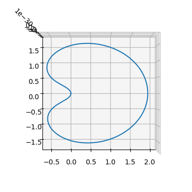
As a sanity check, we first propagate a known periodic Lyapunov-orbit initial condition in zero-thrust mode.
mu = 0.01215058560962404
ic = np.array([5.5643551520142581e-02, 9.2420772211102929e-27, 1.3616512785913887e-31, 2.6173746491479341e-12, 5.2390814115699671e+00, 5.3268092625591314e-30, 1000/MASS])
period = 6.301205688481844
ta_cr3bp.pars[4] = 1./veff_nd
ta_cr3bp.pars[5] = mu
ta_cr3bp_var.pars[4] = 1./veff_nd
ta_cr3bp_var.pars[5] = mu
Propagate the system over one period (zero thrust) to verify the setup.
ta_cr3bp.time=0
ta_cr3bp.state[:]=ic
ta_cr3bp.pars[:4] = [0,0,0,0] # No thrust
sol = ta_cr3bp.propagate_grid(np.linspace(0, period,1000))[-1]
Inspect the trajectory to confirm near-periodicity and consistency of the dynamics setup.
ax = pk.plot.make_3Daxis()
ax.plot(sol[:, 0], sol[:, 1], sol[:, 2], c="black", linestyle="--", label="periodic reference")
ax.legend(loc="upper left", bbox_to_anchor=(1.02, 1.0))
ax.view_init(90, -90)
ax.set_zticks([])
ax.set_aspect("equal")
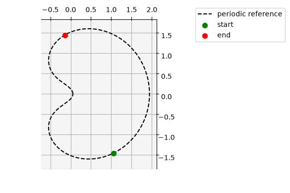
Select two points on the orbit to define initial and final boundary states for a ZOH leg.
ts = -period/3
tf = period/5
ta_cr3bp.pars[:4] = [0,0,0,0] # No thrust
ta_cr3bp.propagate_until(tf, 1000)
xf = ta_cr3bp.state.copy()
ta_cr3bp.propagate_until(ts, 1000)
xs = ta_cr3bp.state.copy()
Visualize these two boundary states on the reference trajectory.
ax = pk.plot.make_3Daxis()
ax.plot(sol[:, 0], sol[:, 1], sol[:, 2], c="black", linestyle="--", label="periodic reference")
ax.scatter(*xs[:3], c="green", marker="o", s=50, label="start")
ax.scatter(*xf[:3], c="red", marker="o", s=50, label="end")
ax.legend(loc="upper left", bbox_to_anchor=(1.02, 1.0))
ax.view_init(90, -90)
ax.set_zticks([])
ax.set_aspect("equal")
Instantiate the ZOH leg in the CR3BP dynamics with the selected boundaries and time grid.
# Instantiate the leg
tgrid = np.linspace(ts, tf, nseg + 1)
controls = [0.0, 0.0, 0.0, 0] * nseg # no thrust
leg_cr3bp = pk.leg.zoh(xs, controls, xf, tgrid, cut=cut, tas=[ta_cr3bp, ta_cr3bp_var])
print("The mismatch constraints are: ", leg_cr3bp.compute_mismatch_constraints())
The mismatch constraints are: [-4.168110301350225e-12, -5.252465129501616e-13, -1.0881432900098286e-41, -5.813849401903326e-12, 2.1009860518006462e-12, -9.693482126966922e-42, 0.0]
Visualize the forward/backward segment propagation and compare with the reference orbit.
def plot_leg(leg, N=100):
    fwd, bck, _ = leg.get_state_info(N=N)
    ax = pk.plot.make_3Daxis()
    ax.plot(sol[:, 0], sol[:, 1], sol[:, 2], c="black", linestyle="--", label="periodic reference")
    ax.scatter(*xs[:3], c="green", marker="o", s=50, label="start")
    ax.scatter(*xf[:3], c="red", marker="o", s=50, label="end")

    for segment in fwd:
        ax.plot(segment[:, 0], segment[:, 1], segment[:, 2], c="blue")
    for segment in bck:
        ax.plot(segment[:, 0], segment[:, 1], segment[:, 2], c="darkorange")

    ax.legend(loc="upper left", bbox_to_anchor=(1.02, 1.0))
    ax.view_init(90, -90)
    ax.set_zticks([])
    ax.set_aspect("equal")
    return ax


ax = plot_leg(leg_cr3bp)
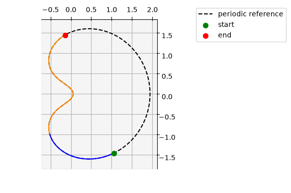
This no-thrust case yields a near-zero mismatch, as expected from consistency with the reference dynamics.
Next, apply non-zero controls to observe how the mismatch changes when boundary states and controls are no longer dynamically consistent.
# Instantiate the leg
tgrid = np.linspace(ts, tf, nseg + 1)
controls = [0.3, 1.0, 0, 0] * nseg # no thrust
leg_cr3bp = pk.leg.zoh(xs, controls, xf, tgrid, cut=cut, tas=[ta_cr3bp, ta_cr3bp_var])
print("The mismatch constraints are: ", leg_cr3bp.compute_mismatch_constraints())
The mismatch constraints are: [-1.0037172748750471, -0.31101434941352546, -2.102304274565298e-30, 0.91693944082219, 0.09178632008572529, 2.6689693736228807e-31, -0.6719599164459205]
ax = plot_leg(leg_cr3bp)
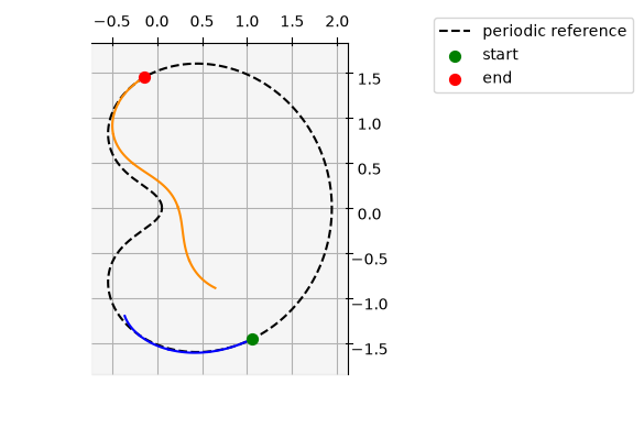
The result is consistent: introducing non-zero controls with fixed boundaries generally increases mismatch unless controls are optimized.